Antenna 2.0
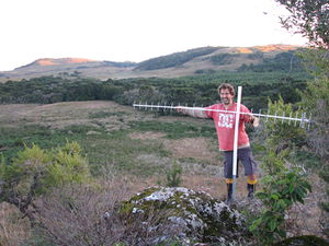
Well here it is, the long-awaited Antenna 2.0 blog post!
Our net's been getting worse and worse over the last year, not only slower, but also we have a long delay before connecting - sometimes more than an hour! And so I thought that a bigger antenna may help by enabling us to use 3G instead of 2G. Even though the problem is mainly with our provider, Vivo, because we often a perfect 5-bar 2G signal, but still have a very slow connection, we figure that a bad 3G connection will be a lot better than a bad 2G connection!
So the first step was to get the metal, thick copper tubing for the boom and thin copper for the wave-guides. Our friend Eduardo happened to have a load of six metre copper tubes - he builds apartments and has a huge "hardware store" below one of them where he keeps all the left overs and spare parts, there's rows of shelves full of pipes and cables and even areas with dozens of porcelain sinks and toilets! The new antenna is three meters, but unfortunately we needed to get it in two pieces to fit on the bus and in our little hire car. He didn't quite have thick enough single-core copper cable for the wave guides, so we went to a metal scrap yard for that and picked up ten metres of uninsulated 3mm diameter copper wire.
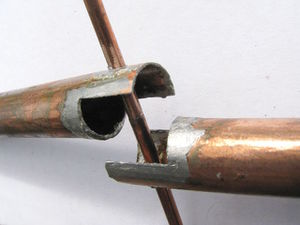
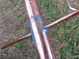
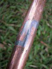
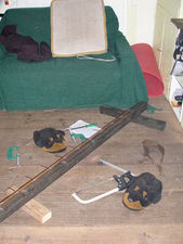
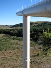
The first part of the construction job was to join the pipe back into a single three meter length. Unfortunately I still haven't bought an acetylene tank for my gas welding kit, so I had to make do with soldering instead of brazing. I cut the ends as shown below to increase the join length and filed the ends at an angle (not shown in the photo) so the solder would still be strong after filing the pipe smooth, and I also positioned the join exactly where a wave-guide would sit to further increase strength...
...but all to no avail, the solder was just too weak to support the weight of such a long length. So I figured that the best way would be to have a section of slightly smaller diameter pipe that fitted inside the main pipe that would support the join from the inside and stop it from bending. But there's no way we'd be making a dedicated trip to the city and searching round for days for a piece of tube just the right size in the near future, so I figured that the project would have to be put on the back burner for a while.
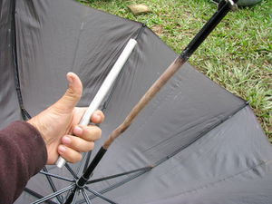
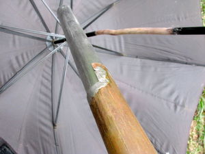
But then a stroke of luck hit, one morning I opened the door, and there was the umbrella which had fallen on the ground and broken into three parts somehow - and you'd never believe it, but the tube that had somehow broken was exactly the right size to use for the antenna join! I quickly fixed the umbrella with a piece of wood as I sensed some rolling pin activity on the brew :-/
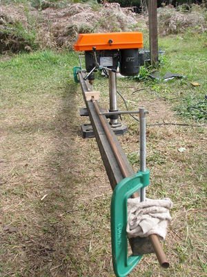
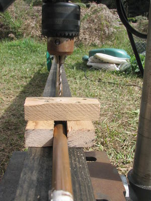
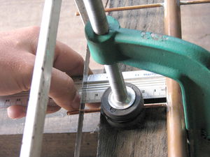
So the next step was to drill the holes for all the wave guides. I needed to ensure that they were all on exactly the same plane without twisting so I clamped the pipe firmly onto a straight piece of wood and made a guide that would ensure that all the holes were in exactly the same position on the pipe.
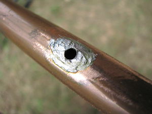
Then next I filed and tinned the holes and soldered the wave guides in. I actually found that soldering them by holding the joins over the gas oven element was easier than the soldering iron because the pipe sucks all the heat away - again brazing them would be by far the easiest and strongest solution. I made sure the metal I soldered in for the wave guides was a few millimetres too long so that I could cut and file them perfectly to length afterwards.
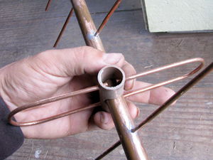
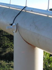
The most difficult part to get exactly the right size and shape is the folded dipole, the bit that the cable joins to. But after a couple of attempts I made one that was accurate to about half a millimetre. I attached it to the boom in a piece of PVC pipe as shown below.
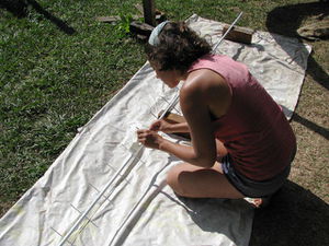
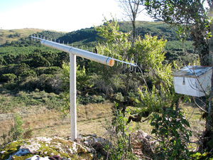
And then the final steps, painting it and putting it up on the hill! Beth's much better at painting than me so she took care of this part :-)
And so what was the final result?!
Well.... kind of mixed results really... it can only get a two bar 2G signal whereas the small one gets a full five bar signal. It picks up a zero or one bar 3G signal which is about the same as the small one, but the 3G connection seems to consistently work, whereas the small antenna's 3G connection is very intermittent. More testing is needed, and there's a few tweaks that can be made to improve performance, but overall the results are rather disappointing :-(
Update: Well I've spent a few days reading, talking to radio engineer friends and doing some adjustments and the result, while not awesome, looks like it has at least achieved the goal of getting us into consistent 3G. First I replaced the metal bolt that was used to mount the folded dipole with plastic, then I mounted the whole thing onto a large PVC pipe so that the antenna can be held very straight since it was bending under it's own weight when not supported.
We've had some very rainy days and misty mornings and our 3G connection has continued to function throughout it all which the small antenna could never have done, so although it's unable to get a decent 2G signal, it's definitely performing more consistently on 3G, and that's the most important thing. We seem to be getting between 500 kilobits and one megabit most of the time, which means we should be able to do voice and maybe even video now :-)
