Our rural net connection
| 1. Moving from Curitiba to Canela | Our power project | |
| 2. Moving on to our land | Our rural net connection | |
| Year on the land: 1 | 2 | 3 | 4 | 5 | 6 | Our first house | |
| Our second house | ||
| Lada Niva |
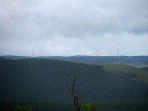
We're in the process of moving on to our land and have started to order some parts to prepare for connecting to our nearest cell tower about 9km away from us for our Internet connectivity. We used this excellent map of cell towers (called ERBs in technical lingo) in Rio Grande do Sul to find the exact location of the ones we can see (update: that site is out of date, now we use Anatel, also their co-ordinates are in an annoying format which you can convert here by entering e.g. 29S210620 as 29°21'06.20"S). Here's a picture of the towers from the big hill about 1km from our house, and a map we've made of out local towers taken from the aforementioned official data. We have almost line-of-sight to these from our small local hill which is only about 200 metres away.
Unfortunately these towers currently only provide a 2G (EDGE) signal, but from our local hill we can pick up unassisted on a USB modem, so with a router and directional antenna, and possibly a powered signal booster too, we should have a pretty good signal. The signal no matter how good will be restricted to 236kbps by the EDGE protocol which is extremely slow, but will still be enough for me to get my work done - and maybe even do some voice chat.
Contents
The router
Routers have an amplified signal which is much better for areas of low coverage than the small USB modems, and also has the advantage of handling the cellular connection internally and providing standard Wifi and/or LAN interfaces (they also provide a standard phone connection so that a normal phone can be used with the cellular connection, but we'll probably not use this feature). The LAN interface is particularly useful because it allows us to place the whole device at the end of a long length of LAN cable and AC power cable, but a USB cable required by a standard 3G modem is restricted to only a few meters of length.
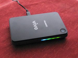
The Vivo stores here in Canela and Gramado took over a month trying to get a Huawei B260a 2G/3G router for us, but still nothing! so we ended up asking Beth's sister to get one from a Vivo store in Brasília and bring it down when she visited in December before Christmas.
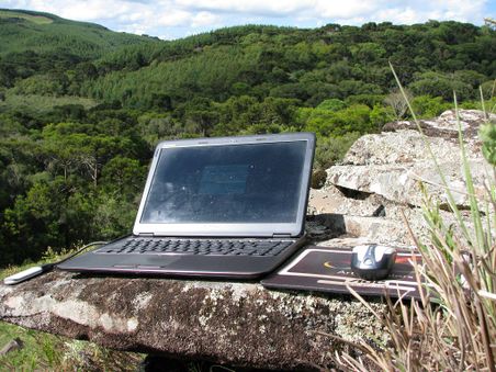
I tested the new B260a out at the "rock office" last week, and it looks very promising for connectivity on the land! I tested it just running unassisted (no amplifier or directional antenna) and although it only got a one-bar signal it was far better than the little USB stick! Although it's only a 236kbps 2G connection it was very consistent and usable, I could check email and surf the net no problem - even pages such as this one with many images loaded no problem. With the USB modem it was only just possible to use, emails would take up to a minute to send, most web pages weren't practical to view with images, and I had to turn off the automatic regular email checking in Thunderbird. So the router is a vast improvement already, but after it's amplified, using the directional antenna and running via LAN cable to the house it should be a perfectly acceptable connection for doing my work from the land :-)
The cable
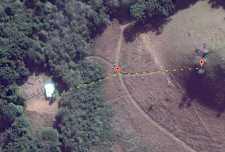
So the first step is to run a LAN cable from the hill where my "rock office" is that picks up a weak 2G connection across to where our house is. The map below shows the direct path between the two points which is about 160 meters, but will probably be a few more since it won't be a perfectly straight path in practice.
I bought a box of 300 meters of Cat 5 cable for R$250 - getting it by the box was the most cost-effective quantity and we'll probably make use of the rest of the cable eventually as we build more dwellings around the land.
We'll just stretch it over the distance held up about 2 meters off the ground by U-nailed into posts about an inch thick hammered into the ground, we can probably find ten or so suitable sycamore branches lying about which will do the trick. For the bush area we can use the existing trees to hold the wire up.
Also, since we need our cable to go about 160 meters but the Ethernet standard restricts us to 100 meters, we'll need to have a powered hub or switch in the middle. The image on the right shows where the cable will run from point "A" (the house), to point "B" the mid-way pole, up to point "C" which is a tree about 10 metres from the Rock Office.
|
|
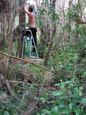
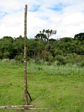
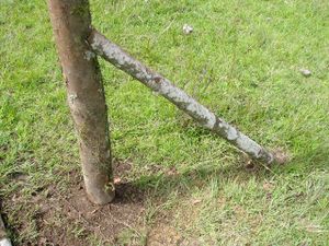
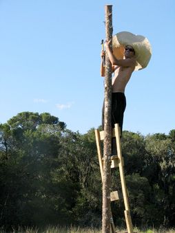
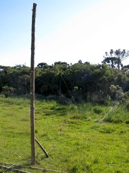
The first problem encountered was that there's about 50 metres of swamp through which we can't put posts into the ground since it's often submerged in a metre or so of water. The first thirty metres or so has some decent sized firmly rooted trees in it which I used instead of poles to support the cable, but there's still about thirty metres where no supports can be placed. So I decided to instead put a single large post about halfway between the swamp and the Rock office destination and have the cable go directly between these points without any additional poles in between. The LAN cable can't support its own weight over that distance though, so the plan is to use fencing wire as the main support and then hang the cable loosely along the fencing wire. Here's some photos of the cable being strung through the swamp area and the pole with one brace (there'll be four braces in all).
|
|
|
DIY PoE (Power over Ethernet)
Of course the LAN connection is not the whole solution, we'll need to have power available at the remote end as well to power the router. But rather than buy another 160m of cable for power I thought it'd be best to use a PoE (Power over Ethernet) solution. And rather than spend extra money buying all the dedicated PoE equipment, we may as well go the gambiarra route and do it with some scissors and tape! the 100BaseTX Ethernet protocol only uses two of the four twisted pairs in the CAT5 cable (the orange and green pairs), so we can simply chop the cables and inject power into the spare (brown and blue) pairs ourselves. A quick search for diy poe shows that this is a very popular approach! Basically the idea is to separate out the brown and blue pairs, twist each pair together and use one pair for positive power and the other for negative.
One serious issue we have to solve that most DIY-PoE'ers don't have to worry about though is that the resistance of 160 metres of cable will lead to a very significant drop in the voltage at the remote end. Trying to account for this drop by using a higher voltage at the source end is risky, because the voltage that reaches the equipment is then dependent on the current that the equipment draws, and this changes considerably depending on how active the equipment is at any given time. A further issue is that we need to power equipment not only at the end, but in the middle too which means we have two different voltage drops to account for.
My idea for getting round this problem is to use a transformer to step down the 220v AC output of the inverter to a lower voltage such as 12v which is safe to put into the Ethernet cable's spare pairs, but as AC instead of DC. At the other end (and in the middle) an identical transformer is connected the other way round to step the low AC voltage back up to a high AC voltage again to power the equipment (the switch in the middle and the router and 2G amplifier at the remote end).
The reason this approach will work is because all the equipment uses power adapters that employ switched-mode power supplies that can accept a wide range of AC input voltage usually between 100vac and 240vac (this is done so that the same adapters can be used in all international areas regardless of their voltage requirements). This means that even with a voltage drop of 50%, the step-up transformer would still bring the dropped low voltage supply up to 120v AC which is still well within the acceptable supply range for the equipment's power adapter to operate from.
I've bought some 50W halogen lamp transformers which should do the trick, they're a design that allows either 110vac or 220vac on the primary side and deliver 12vac on the secondary. This means that it would also be possible to put 220v into the 110v primary configuration to deliver 24v on the secondary, but keep the remote transformers in the normal 12v-to-220v reverse configuration - this would be necessary if the voltage drop were greater than 50%, but I'm only expecting a drop in the region of 10%.
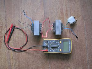
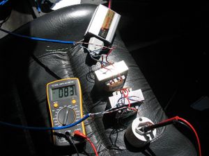
I did an initial test to ensure the general idea will work ok with the transformers I bought. Here's a picture showing two of the transformers connected together by their 12v secondary sides, with the first one's primary side ready to connect into the mains 220v power source, and the voltage meter ready to measure the output (primary) side of the second transformer. I tested it using the 200W power inverter in the car rather than the mains power in the pensão though just in case it blew up or something! but luckily it didn't blow up, it just made a bit of a hum, and gave the correct measurement of 220v AC and drew negligible current - whew! :-)
 the basic configuration |
 coiled parallel pairs, no load |
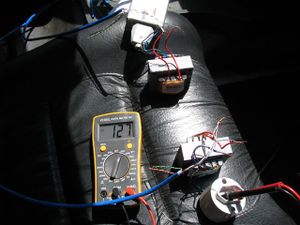 coiled separate pairs, no load |
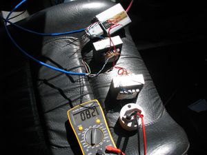 uncoiled parallel pairs, no load |
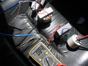 uncoiled separate pairs, no load |
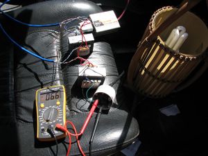 15W load and uncoiled separate pairs |
Above are the results of testing the transformers connected via 120 metres of LAN cable. I've used the term "coiled" to refer to when the LAN cable was in a big coil rather than stretched out in a long length (of course in reality it will not be coiled, but I wanted to see what difference this made to the results). The term "separate" pairs is when each of the two LAN pairs contain both phase and neutral AC current, and "parallel" is when one pair is joined to the phase side and the other to neutral. Separate/parallel made a lot of difference when coiled, but not when straight which is what we're interested in. Here's a good voltage drop and cable size calculator.
Well so much for my expectations of a 10% drop! Unfortunately these results point towards the PoE solution being infeasible for our situation because over this distance, something like 20W of power will be wasted as heat radiating out of the cable. It would help if we could use a other transformers that work with a higher voltage (say 50vac) so that the I2R losses are reduced, but then there's the additional problem that the higher the AC voltage running very close in parallel to the signal pairs, the more they will interfere. So overall it looks like it'll be best to get some power cable which will have very minimal loss since it's designed to carry power effectively and will have 220v in it thus drastically reducing the I2R losses.
The pole
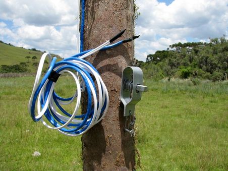
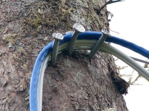
I took the transformers back today and luckily the hardware store was nice enough to refund me the R$60 for them, I then bought 100 metres of 2x1mm power cable for about R$90 which is enough to get the first half of the cabling in place. I attached the power and network cables in alternate positions along the fencing wire to try and avoid them running in parallel as much as possible and attached a wire tightener at the bottom of the pole (shown in the pictures below) to make it easy to tighten the wire and raise the cables without needing to use a ladder. The last of the four pictures below shows the raised cables going to the pole with the tree at the top of the tree in the background which is the final destination of the second half of the cabling.
|
|
|
|
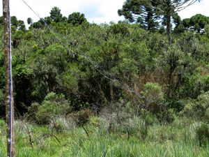
|
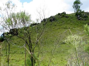
|
Mounting the equipment
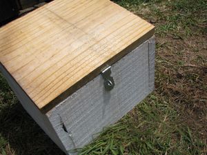
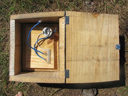
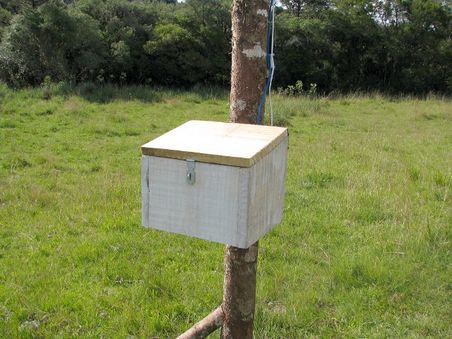
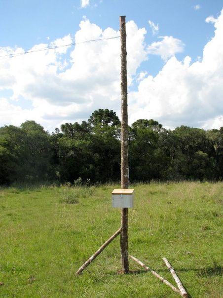
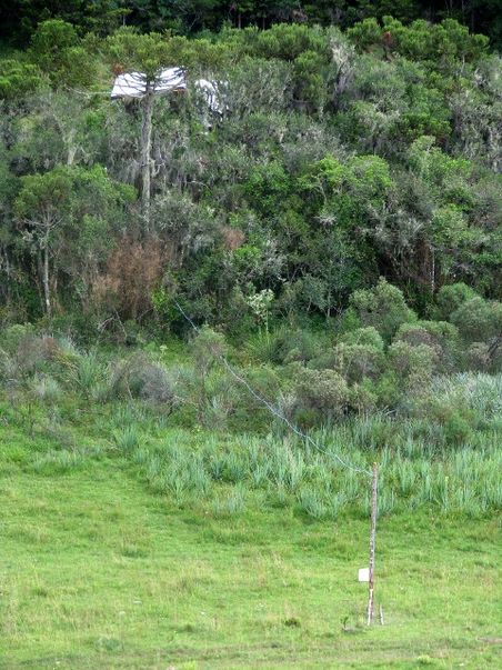
Now that the first half of the cable is in place, we need it to run into a weather-proof box attached to the pole where a hub will be mounted to join the first and second network segments together. Such boxes turned out to be pretty expensive and I really didn't see the point of such expense when it seemed pretty trivial to hammer together a couple of boxes from some of our spare house wood that would do the trick - if any water enters in through any cracks in the wood it's only going to dribble down the sides, so the only thing we need to do is ensure that the equipment is mounted away from any contact with the sides. Here's some pictures of the box for the hub, I used some weather proof tape to cover the hinges along the back since there was quite a wide crack there, and I made a small removable raised platform in the bottom so that the equipment isn't in contact with the sides or bottom which may become wet in bad weather.
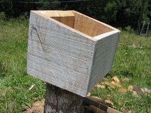
|
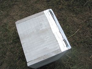
|
|
|
|
|
|
The second cable segment
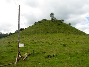
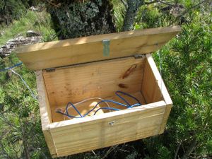
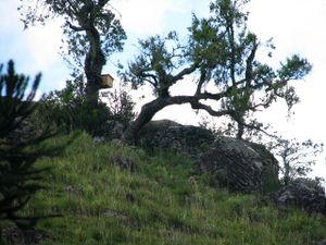
The distance to cover for the second half was about 100 meters which is longer than expected - I think due to making an error in the original distance calculation; I said that it was 160m on the map, but that it should be less than that in reality since its a hill and we'd be stretching the wire straight - but the 160m map length is already the straight length and in reality we can't stretch it completely straight, so its longer than 160m. I made a second box similar to the first but a little bigger since it will potentially need more equipment and maybe some tools in it.
|
|
|

| ||
Testing the cables
First I got both segments of power cable tested which was the easy part, I just plugged the generator in at the house in and then tested the loaded and unloaded voltage at the middle pole, then when that looked good, I connected the two segments and tested again at the far end which also looked good. There was some drop but the final loaded voltage was around 105 volts which is fine.
I then I tested each segment of the LAN cable by plugging the router into the power and LAN at one end and checking if I could reach it with my laptop at the other end. Both LAN segments tested fine, so the next was the big test - put the router at the far end up the hill (on top of the box since there's no antenna yet), plug the hub into the power in the middle box and both LAN cables into it, then see if we have net!

|
|

|
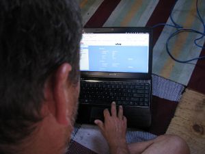
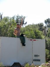
The first picture above was me after first establishing a connection with the router at the top of the hill, the second shows the router's web interface after having made contact with the Vivo tower, and the third is me making our very first wiki edit from the house.
The antenna
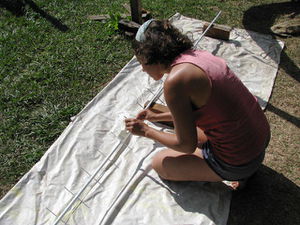
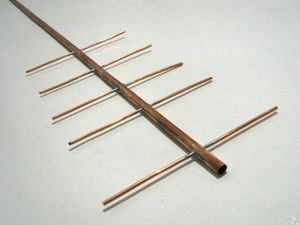
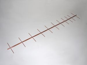
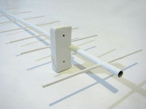
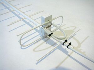
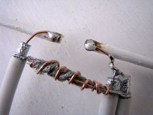
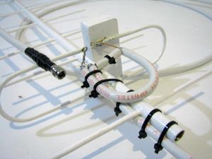
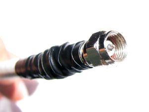
It's quite difficult finding decent antennas tuned to 850MHz for 2G and those that can be located are around R$200 which seems outrageous considering they're only made from about $5 of parts, so I've decided to go the DIY route for this too! I found this excellent page by Damon Chandler which has very clear instructions on how to make a pretty good one. He uses John Drew's Yagi Calculator to determine the exact measurements you'll need for your required frequency and the dimensions of the materials you'll be using, his formulae are optimised for 10, 14, 19 or 24 element antennas. This means I can go to the hardware store and get whatever they have available that looks best and then make a design that exactly matches these parts.
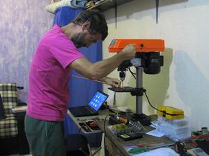
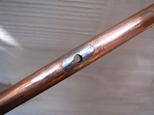
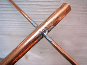
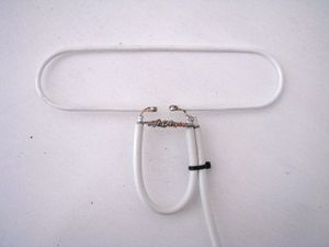
I picked up a drill press from the local hardware store for a really good price, so that made drilling the holes for the wave-guides much easier and more accurate. It's quite difficult to solder such large areas of metal because it acts as a heat sink, so I first tinned the areas (added solder and filed flat again) to be soldered and then redrilled them before soldering each wave-guide into place. The folded dipole was the most difficult bit to get right, the inner radius of the curves needed to be 35mm and the total width 173mm with the small gap in the exact centre. I got it pretty close to sub-mm accuracy.
|
|
|
|
|

|
|
|
|
|
|
|
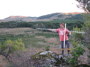
The next weekend we went to the land with the antenna ready for testing on the hill! I took the antenna, router and laptop up the hill so that I could look at the signal strength while adjusting the position of the antenna. First without using only the router's internal antenna I got a usable connection of one bar. Then I plugged the antenna in and it dropped down to zero connection, but then when I put the antenna in the branches of a nearby bush so that it was pointing in approximately the right direction, the connection went up to two bars, and then a few seconds later after I started loading some pages, the connection went up to a full five bars and stayed there persistently!
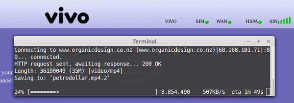
This result was better than I had dared to hope for! it looks like being a perfectionist and making everything to sub-millimetre accuracy and smoothing off all the rough bits of metal really paid off :-) But it gets even better! it turns out that the rural VIVO towers do actually have 3G capability, but since the towers have to cater for mainly long-distance users they provide it over the 850MHz band instead of the usual 2.1GHz - and my connection was now good enough for the "w850" option to become available! When I selected this the connection changed from EDGE to WCDMA and the signal dropped down from five bars to only two bars, but the connection was still very responsive and usable - and more importantly was working about five times faster than the five-bar 2G signal! I did a speed test and was getting a consistent one megabit connection - a far better result than I could possibly have hoped for!
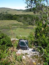
I also decided that since the results were so good, it would be worth testing at our house as well. Holding the antenna up on top of the trailer in the general direction of the tower (with a large hill in the way) got a usable one-bar 2G signal, so I'd say that we could get three bars using a small tower, but we probably need it on top of the hill to have any chance of using the 3G connection.
|
|
|
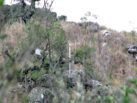
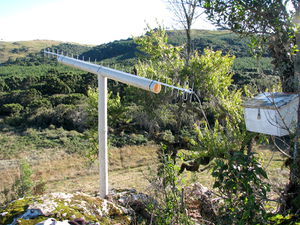
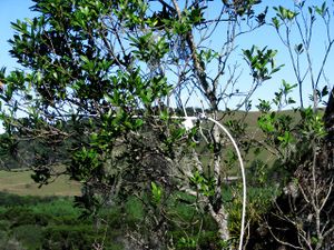
After more than a year I finally installed it properly with a pole set into the rocks with concrete. This photo is taken from our house zoomed up onto the top of the hill.
Antenna version 2.0
I've got some 15mm diameter copper tube and some 3.5mm thick coper wire ready to get started on a new antenna with 24 elements, which will be over 3m long! The reason is that our 3G signal is usually too bad to be usable, and to get 3G the antenna needs to be in a slightly different angle for some reason, but that angle is bad for 2G. I figure that we only need a little more gain for the 3G to be usable even when the signal's at its worst - and I think a 24 element one should give us quite a bit more gain! Also, our account now has 4G available on it, so it will be interesting to see if our rural tower also provides that over 850MHz too :-)
In mid 2015 I finished the new antenna, see the Antenna 2.0 blog post for the construction details.
After using the net on the new antenna for about six months we can say with certainty that the signal is much better. It was hard to tell because the bandwidth has been getting much worse regardless of the signal, most likely due to Vivo taking on more customers without upgrading their hardware.
But then in late November 2015, our net connection suddenly got way better, we suddenly started getting a full strength signal on 3G with consistently 2-3 megabits of bandwidth peaking over 4 megabits! I guess they must have finally upgraded our tower!
Putting the cables into PVC pipe
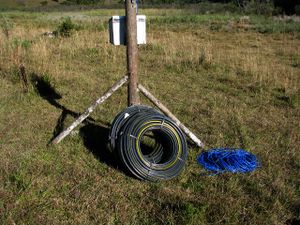
The cables had got much more badly damaged since last time I checked and the net wasn't working, and unfortunately the job of getting the cables through the PVC pipe was far more difficult than expected :-( my plan was to use a weight tied to string to use gravity to pull string through and then pull the cables through with the string.
|
|
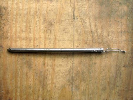
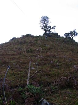
A thin cylindrical lead fishing sinker would be ideal, but I didn't have anything like that, so instead I made a weight using a six inch nail with the end chopped off. The first problem we encountered was that just lifting segments of the pipe to create a locallised incline for the weight to slide down didn't provide enough force to pull the string after about twenty metres, but we found that laying the pipe down the side of the hill solved this problem very well and the weight could be coaxed through quite easily.
|
|
Unfortunately the next problem wasn't so easily solved; the string wasn't strong enough to pull the cables through. The cables have quite a bit of resistance and as the distance gets longer the resistance multiplies. After about thirty metres the force required to pull the cables was more than the string could bear and it broke! We tried various other approaches such as putting the string through again and then using it to pull fencing wire through which would in turn be used to pull the cables through, but everything we tried failed in one way or another.
Beth did a day-mission to Canela to get some strong fishing line which should be even easier to get through the pipe than the string, yet strong enough to pull the cables through directly without requiring the intermediate step of putting fencing wire through first. She left at 7am to catch the 9am bus and then came back on the 2pm bus with some strong fishing line made for reeling in thrashing 55Kg fishes and also some thick nylon string as a backup measure. Both of them were so strong that I was unable to break them while wearing thick leather gloves.
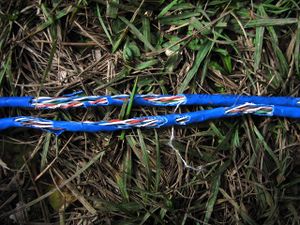
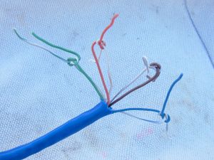
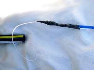
We got up early and had some breakfast and lemon tea and then both went up the hill about 9am to try the process again. The nail went through quite easily with the fishing line, and then I attached it at the bottom to the cables. We needed to ensure that the connection was extremely strong since a lot of force would be required to pull the cables through. I put a double knot on every pair of the LAN cable and knotted the power cable in two places then knotted the fishing line through all these other knots. I then put insulating tape around it all to ensure there were no rough edges to cause unwanted friction.
|
|
|
The force required to pull cables through was extreme, it was much more than when we were pulling them through last time with the fencing wire. I'm pretty sure the problem is due to the cables being coiled and uncoiled over the last couple of days which has made them much less straight and therefore causes much more friction. It took about two hours to pull them through and it was incredibly tiring, each strong pull would bring in only 10 or 20cm and it would have to be held firm before the next pull otherwise it would recoil back in again! but it did finally get through at last!
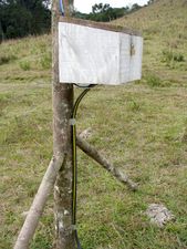
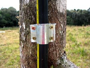
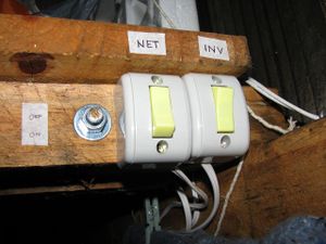
I then attached the cables into the pole and laid the PVC pipe through the swamp into our house, installed a couple of switches for turning the inverter and net power on and off, and whipped up a couple of metal braces from some roofing iron scraps to fasten the pipe firmly to the pole. I'll also need to peg it to the ground to prevent cows tripping on it.
|
|
|
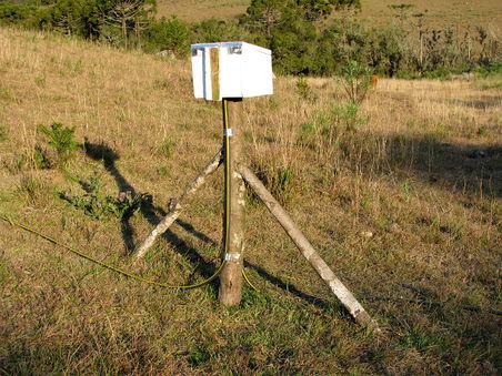
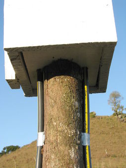
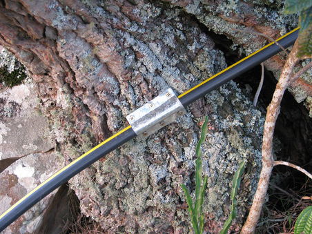
We didn't get the second segment done for another couple of months, but on August 6th and 7th I finally decided it was time to bite the bullet and get on with it! it was a lot easier this time as we knew what we were doing, we had the strong fishing line prepared and the cables of the second segment were very straight since they'd been hanging over head for some months. But even with all these positive things on our side and absolutely nothing going wrong at all, it was still a long difficult job taking a full day to complete! We got the cables through the PVC pipe in the morning which took a couple of hours, and then I chopped the pole and put the box on top with the pipes going cleanly in the bottom. Everything's much more solid now, all the cable connections are soldered and all the pipes go right into the boxes so that there no cable at all exposed to the outside world :-)
|
|
|
|
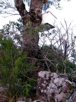
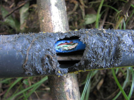
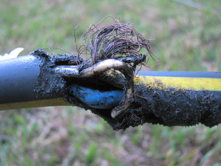
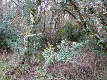
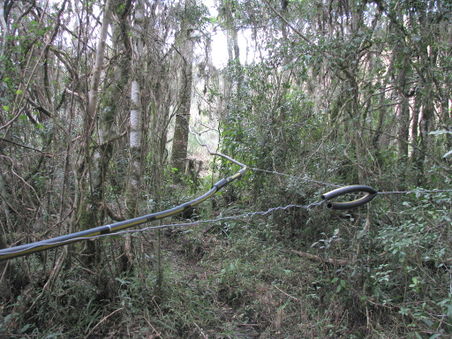
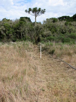
Unbelievably we started having trouble with the connection again about a year later and it turned out that Giant swamp rats hat chewed through the cable! So now I've cleared the bush and installed the cable a metre or so above the ground as shown here.
 |
 |
 |
 |
 |
Signal booster
Unfortunately the signal has degraded and we no longer have 3G, only a 3-bar 2G signal which is pretty frustrating to use. So the next thing to try is boosting the signal strength with a powered amplifier. Most of these are in the form of repeaters which have two antenna connections, one for an external antenna that points to the tower, and another for an internal antenna which connects to the local devices such as routers and cell phones. Instead of using the internal antenna, I would directly connect the router's external antenna connector with the repeater's internal antenna connector. Here's some options I've found for 850MHz:
A friend of mine who's an RF expert thinks that a direct connection between the repeater and the router may introduce too much gain into the system and that I may well need to put an Attenuator between them. He suggested I build a simple switched unit like this that would allow me to adjust the attenuation to find a suitable setting.
Hub and indicator light
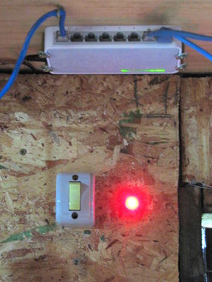
In May 2014 we installed a hub so that Beth and I (and also guests) can all use the net at the same time without needing to waste power running a wifi router. Also we found that many Ethernet ports are unable to drive the 100m LAN cable directly, so the hub solves that problem too. The hub power adapter needed to be connected to the power that goes to the PVC pipe so that it's only switched on when the net router is switched on. I also spliced into the 9V DC supply to the hub to put a red LED in the wall to indicate when the net is switched on because many times we've accidentally left it running for many hours consuming precious power! The photo below shows the current setup which has all the wiring hidden nicely behind the wall panel and the hub attached to the bottom of the loft floor.
Antenna on the big hill
Unfortunately our net is just not working out very well with the antenna on the small hill as the line of sight to the towers is blocked by a bigger hill about a kilometre away. Also another problem is that the company we're using, Vivo, is really bad and often only gives us a fraction of the bandwidth we have available, but they're the only provider we have a signal available for on the small hill. On the large hill we have direct line of sight to towers for Vivo, Claro and Oi so not only would we have a much better full-time 3G connection, but we'd also have the option to change to a better company when we need to.
The land on the top of the big hill is owned by our neighbour, Devalso, who has said he'd be happy for us to put an antenna system up there. But The top of the hill is too distant to run any cables to, so we need it to be solar powered and deliver the signal to us via wifi. This means it will need it's own battery, charge-controller and inverter.
Another problem is that since there's no cables we can't turn it on and off via a simple switch which means that either we need a more exotic way of controlling its power, or we need a bigger battery and more solar panels to handle it running all day and night.
One interesting method of turning it on and off remotely is to use a laser on our house aimed at the system, and have a small low power circuit to detect the light from it and power it up. The box on the hill could have a tube pointing down towards our house so that the sun doesn't shine onto the detector confusing it.
Passive repeater on the big hill
Putting a powered repeater, or the router at the top of the big hill is very complicated and expensive as it requires a solar panel, battery, charge controller and inverter. But I suddenly had an idea - couldn't you have to directional antennas at the top of the hill, one pointing and the tower and one down to our house, and simply connect them together? Wouldn't that redirect the power at that frequency over the hill? I did a little research and found that this idea is one form of "passive repeater" and has been used with some success by others. There's some links to discussions about them here, here and here.
People say it doesn't work very well but does offer a functional signal where there wasn't one before. At the moment we have a zero-bar signal for 3G that does connect but doesn't really work. If this method increased the signal just a little we should be able to get consistent 3G with it.
People say the cable should match the antennas well in impedance. Some say the cable should be as short as possible, but others also say that the two antennas should not be too close so that they don't interfere with each other.
Lessons learned
- Wood is an insulator and so doesn't usually affect a signal, but when its filled with water after heavy rain it can reduce the signal strength a lot if its close to the antenna.
- Actually the antenna works best if it's not close to any other thing. Our signal went from one bar to five bars just by raising it up a metre or so away from the rock and bushes it was sitting on.
- A PVC pipe in which to carry the wires is essential, it's unbelievable how quickly the rubber perishes and wears.
- Don't use a pipe that's only just big enough, allow a bit of extra space as it will save a lot of energy even though it costs a bit more.
- Try and keep your cables straight and avoid tight coils to reduce friction.
- Use very strong string even if you don't think you'll need it.
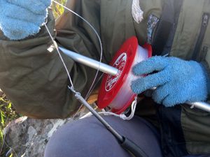
- Don't just lay the string on the ground when you're pulling the cables through, wind it onto a spindle in case you need to do it again!
- Apparently there's a special kind of wire used for this that can be pushed into the pipe instead of using a weight.
- If you chop LAN cables to use them to connect to your other cabling, don't assume that they use the proper TIA/EIA-568 standard for having the colours assigned to the correct pins
- A yagi of more than 12 elements is not efficient, better to use a dish or stacked yagi configuration, see this comment on the yagi page
