Difference between revisions of "Smart battery"
m |
(→Resetting the EEPROM: chinese battery hacking shop) |
||
| (2 intermediate revisions by the same user not shown) | |||
| Line 6: | Line 6: | ||
== Resetting the EEPROM == | == Resetting the EEPROM == | ||
| − | Many batteries stop working after a predefined number of charge/discharge cycles, but instead of replacing the battery, it's possible to reset this counter as the battery's data is stored in an EEPROM. There is software available that gives easy access to the information in many models of battery, for example here's a screenshot from [http://sbworkshop.com SBWorkshop2]. There's also some free utilities for Linux such as [http://frantisek.rysanek.sweb.cz/battery.html this one]. | + | Many batteries stop working after a predefined number of charge/discharge cycles, but instead of replacing the battery, it's possible to reset this counter as the battery's data is stored in an EEPROM. There is software available that gives easy access to the information in many models of battery, for example here's a screenshot from [http://sbworkshop.com SBWorkshop2]. There's also some free utilities for Linux such as [http://frantisek.rysanek.sweb.cz/battery.html this one], and on the right a picture of a typical battery and its internal parts. |
| + | {| | ||
| + | |[[File:Smart battery workshop.gif|390px]]|| ||[[File:Inside typical laptop battery.jpg]] | ||
| + | |} | ||
| − | [[ | + | Most of the complexity in these devices is actually in enabling the computer to communicate over an SMB two-wire channel which isn't available on a normal laptop, desktop, server or handheld device. But the very basic devices like the Arduino and [[Raspberry Pi]] are designed for hardware-oriented projects and come with SMB communications as standard since that's how most chips and cards communicate. See also [http://www.pcpop.com/doc/0/413/413518_all.shtml this page] showing a typical Chinese battery hacking store's procedure :-) |
| − | + | == SMBus == | |
| + | The [[w:System Management Bus|System Management Bus]] (abbreviated to SMBus or SMB) is a single-ended simple two-wire bus for the purpose of lightweight communication, and was defined by Intel in 1995. It carries clock, data, and instructions and is based on Philips' [[w:I²C|I²C]] serial bus protocol. Its clock frequency range is 10 kHz to 100 kHz. Its voltage levels and timings are more strictly defined than those of I²C, but devices belonging to the two systems are often successfully mixed on the same bus. | ||
| + | |||
| + | When mixing devices, the I²C specification defines the VDD to be 5.0 V ±10% and the fixed input levels to be 1.5 and 3.0 V. Instead of relating the bus input levels to VDD, SMBus defines them to be fixed at 0.8 and 2.1 V. This SMBus specification allows for bus implementations with VDD ranging from 3 to 5 V. | ||
| + | |||
| + | The [[Raspberry Pi]] comes with SMBus as a standard means of connectivity and configruation is done as shown [http://learn.adafruit.com/adafruits-raspberry-pi-lesson-4-gpio-setup/configuring-i2c here]. | ||
== See also == | == See also == | ||
Latest revision as of 04:06, 28 June 2013
Smart Battery System (SBS) is a specification for determining accurate battery capacity readings, usually for a laptop. It allows operating systems to perform power management operations based on remaining estimated run times. Through this communication, the system also controls the amount the battery is charged. Communication is carried over an SMBus two-wire communication bus. The specification originated with the Duracell and Intel companies in 1994, but was later adapted by several battery and semiconductor makers.
The Smart Battery System defines the SMBus connection, the data that can be sent over the connection (Smart Battery Data or SBD), the Smart Battery Charger, and a computer BIOS interface for control. In principle, any battery operated product can use SBS, but in practice only laptop computers use the system.
A special chip in the battery pack monitors the battery and reports information to the SMBus. This information might include battery type, model number, manufacturer, characteristics, discharge rate, predicted remaining capacity, an almost-discharged alarm so that the PC or other device can shut down gracefully; temperature and voltage to provide safe fast-charging.
Resetting the EEPROM
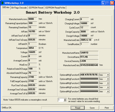
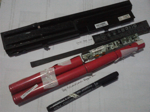
Many batteries stop working after a predefined number of charge/discharge cycles, but instead of replacing the battery, it's possible to reset this counter as the battery's data is stored in an EEPROM. There is software available that gives easy access to the information in many models of battery, for example here's a screenshot from SBWorkshop2. There's also some free utilities for Linux such as this one, and on the right a picture of a typical battery and its internal parts.
 |

|
Most of the complexity in these devices is actually in enabling the computer to communicate over an SMB two-wire channel which isn't available on a normal laptop, desktop, server or handheld device. But the very basic devices like the Arduino and Raspberry Pi are designed for hardware-oriented projects and come with SMB communications as standard since that's how most chips and cards communicate. See also this page showing a typical Chinese battery hacking store's procedure :-)
SMBus
The System Management Bus (abbreviated to SMBus or SMB) is a single-ended simple two-wire bus for the purpose of lightweight communication, and was defined by Intel in 1995. It carries clock, data, and instructions and is based on Philips' I²C serial bus protocol. Its clock frequency range is 10 kHz to 100 kHz. Its voltage levels and timings are more strictly defined than those of I²C, but devices belonging to the two systems are often successfully mixed on the same bus.
When mixing devices, the I²C specification defines the VDD to be 5.0 V ±10% and the fixed input levels to be 1.5 and 3.0 V. Instead of relating the bus input levels to VDD, SMBus defines them to be fixed at 0.8 and 2.1 V. This SMBus specification allows for bus implementations with VDD ranging from 3 to 5 V.
The Raspberry Pi comes with SMBus as a standard means of connectivity and configruation is done as shown here.
See also
- SBS Forum, including SBS specification
- Things yo do with your dead laptop battery
- SBWorkshop - a device and application for reading and writing battery data
- Free version of the application for Linux


