Difference between revisions of "Process a scanned diagram"
(→Add an image map: image map links added) |
|||
| Line 1: | Line 1: | ||
{{procedure|There's a few processes which are usually required to be performed on a scanned image before uploading into the wiki which are outlined in [[Process a scanned diagram]]}} | {{procedure|There's a few processes which are usually required to be performed on a scanned image before uploading into the wiki which are outlined in [[Process a scanned diagram]]}} | ||
| − | + | __NOTOC__ | |
| − | [[Image:Example-diagram-1.jpg | + | <br><br> |
| − | + | [[Image:Example-diagram-1.jpg]] | |
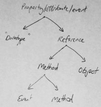
| + | The image shown above is an example of a scanned diagram which will serve to show the effect of each processing step. | ||
These instructions apply to GIMP. | These instructions apply to GIMP. | ||
| − | |||
== Discard redundant colour information == | == Discard redundant colour information == | ||
| Line 12: | Line 12: | ||
will make the converted results more consistent, and will increase compression efficiency. | will make the converted results more consistent, and will increase compression efficiency. | ||
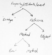
The image to the right demonstrates the removal of the colour information from our example image. | The image to the right demonstrates the removal of the colour information from our example image. | ||
| + | <br><br><br><br><br><br><br><br> | ||
<div class=visual-clear></div> | <div class=visual-clear></div> | ||
| Line 23: | Line 24: | ||
brightness range to target range. All the tools offer a preview which may have to be ticked to | brightness range to target range. All the tools offer a preview which may have to be ticked to | ||
enable. The curves were adjusted on our example image yielding the image to the right. | enable. The curves were adjusted on our example image yielding the image to the right. | ||
| + | <br><br><br><br><br><br><br> | ||
<div class=visual-clear></div> | <div class=visual-clear></div> | ||
| Line 36: | Line 38: | ||
bring up the channels dialog, right-click on the channel named "grey" and select ''Channel to selection''. | bring up the channels dialog, right-click on the channel named "grey" and select ''Channel to selection''. | ||
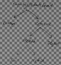
GIMP will render the transparency as a chequer pattern as shown in the image to the right. | GIMP will render the transparency as a chequer pattern as shown in the image to the right. | ||
| + | <br><br><br><br><br><br> | ||
<div class=visual-clear></div> | <div class=visual-clear></div> | ||
| Line 47: | Line 50: | ||
the transparency is locked in the layers dialog, then simply paint over the areas with the appropriate | the transparency is locked in the layers dialog, then simply paint over the areas with the appropriate | ||
brush and colour, with the transparency locked, only the black will be affected, not the background. | brush and colour, with the transparency locked, only the black will be affected, not the background. | ||
| + | <br><br><br><br><br><br><br><br> | ||
<div class=visual-clear></div> | <div class=visual-clear></div> | ||
| Line 57: | Line 61: | ||
== Add an image map == | == Add an image map == | ||
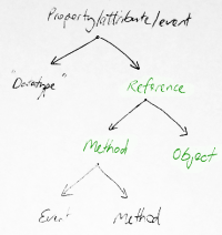
| − | The [[MW:Extension:ImageMap|ImageMap extension]] is installed by default on all Organic Design wikia since [[9 July 2007]]. There is an online tools for creating the coordinates and ImageMap syntax for the different linkable areas [http://tools.wikimedia.de/~dapete/ImageMapEdit/ImageMapEdit.html?en here]. Below is the final result of our processed example image with links added and placed onto a non-white background to demonstrate (badly!) the transparency. | + | The [[MW:Extension:ImageMap|ImageMap extension]] is installed by default on all Organic Design wikia since [[9 July 2007]]. There is an online tools for creating the coordinates and ImageMap syntax for the different linkable areas [http://tools.wikimedia.de/~dapete/ImageMapEdit/ImageMapEdit.html?en here]. Below is the final result of our processed example image with links added and placed onto a non-white background to demonstrate (badly!) the transparency. The ImageMap syntax used is shown beside it and was all generated by the online tool. |
| + | <table cellpadding="0" cellspacing="0"><tr><td> | ||
<table border="1" bgcolor="#ffff80" cellpadding="10"><tr><td> | <table border="1" bgcolor="#ffff80" cellpadding="10"><tr><td> | ||
<imagemap> | <imagemap> | ||
| Line 66: | Line 71: | ||
desc none | desc none | ||
</imagemap> | </imagemap> | ||
| − | </td></tr></table> | + | </td> |
| + | </tr></table> | ||
| + | </td> | ||
| + | <td> </td> | ||
| + | <td valign="top"> | ||
| + | <pre> | ||
| + | <imagemap> | ||
| + | Image:Example-diagram-5.png | ||
| + | rect 70 120 119 144 [[Method]] | ||
| + | rect 148 126 198 154 [[Object]] | ||
| + | rect 108 65 174 91 [[Reference]] | ||
| + | desc none | ||
| + | </imagemap> | ||
| + | </pre> | ||
| + | </td> | ||
| + | </tr></table> | ||
Revision as of 06:54, 8 July 2008
| Process a scanned diagram Organic Design procedure |
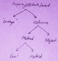 The image shown above is an example of a scanned diagram which will serve to show the effect of each processing step.
These instructions apply to GIMP.
Discard redundant colour information
If the image has no useful colour information such as in the case of a white-board diagram or
pencil/pen diagrams, convert the image to greyscale from the image/mode menu. This step
will make the converted results more consistent, and will increase compression efficiency.
The image to the right demonstrates the removal of the colour information from our example image.
Adjust the contrast attributes
Usually the scanned image will not range from complete black to white and may have inconsistent
shading. The main tools for handling this are Brightness-contrast, Levels and Curves,
all in the Colors menu. Brightness-contrast is the most basic and easilt understandable,
Levels is good for ensuring that the image fills the range properly from black to white, and
Curves (my personal favourite) allows direct visual control over the transformation from current
brightness range to target range. All the tools offer a preview which may have to be ticked to
enable. The curves were adjusted on our example image yielding the image to the right.
Make the background transparent
We can't be sure that the image will always be used on a white background, so its best if it's given transparency and saved in PNG format. Unfortunately IE browsers before version 7 require JavaScript hacks to allow PNG's to render with transparency.
The most accurate way of converting the image from white-to-back to transparent-to-black without any
loss of information is to convert the greyscale channel to a selection, fill the selection black in a
new layer, then discard the original background layer. To convert the greyscale channel to a selection,
bring up the channels dialog, right-click on the channel named "grey" and select Channel to selection.
GIMP will render the transparency as a chequer pattern as shown in the image to the right.
Change colour of selected areas of text
Sometimes its useful to convert some of the text to a different colour again. In this example we'll convert some of the words to green and use the Image map extension to make the green words into links.
First we'll need to convert the image from greyscale back to RGB from the Image/Mode menu. Next ensure
the transparency is locked in the layers dialog, then simply paint over the areas with the appropriate
brush and colour, with the transparency locked, only the black will be affected, not the background.
Resize and upload the image
Most in-wiki images don't need to be larger than the screen or the size they'll be used at, but an exception would be when the detail of high resolution is required, or when the image may be used for printing purposes, but most often such images don't belong in the wiki.
Resize the image in Image/Scale then export as a PNG, and upload it into the wiki.
Add an image map
The ImageMap extension is installed by default on all Organic Design wikia since 9 July 2007. There is an online tools for creating the coordinates and ImageMap syntax for the different linkable areas here. Below is the final result of our processed example image with links added and placed onto a non-white background to demonstrate (badly!) the transparency. The ImageMap syntax used is shown beside it and was all generated by the online tool.
|
<imagemap> Image:Example-diagram-5.png rect 70 120 119 144 [[Method]] rect 148 126 198 154 [[Object]] rect 108 65 174 91 [[Reference]] desc none </imagemap> |
