Difference between revisions of "Our power project"
(→See also: LED over 100% efficient) |
(→Solar panels 2.0: broken cells) |
||
| Line 160: | Line 160: | ||
== Solar panels 2.0 == | == Solar panels 2.0 == | ||
The first panel design has some problems which allowed moisture to accumulate on the inside and also has allowed the cells to bend and crack. They seem to have settled to a final position where no more damage is occurring, but some of them have cracked all the way across, other have just small bits broken off. | The first panel design has some problems which allowed moisture to accumulate on the inside and also has allowed the cells to bend and crack. They seem to have settled to a final position where no more damage is occurring, but some of them have cracked all the way across, other have just small bits broken off. | ||
| − | + | {| | |
| + | |[[File:Broken cell 1.jpg|300px]] | ||
| + | | | | | | ||
| + | |[[File:Broken cell 2.jpg|300px]] | ||
| + | |} | ||
I'm ording another forty or maybe eighty cells from [http://produto.mercadolivre.com.br/MLB-490553153-kit-40-celulas-solares-painel-fotovoltaico-152w-_JM this place] which is doing packs of forty for R$289. This time I'm going to do the design slightly differently whereby the cells will be placed face down onto the glass and then glued in place with silicon on the backs and edges of the cells. Then the plywood backing and the glass will be held only slightly separated by some spacing material around the edges and bolted together. The spacing will be inset slightly from the edges to allow for silicon to be put all around the edge to keep it water-tight. A silicon moisture absorber will be placed inside the panel as well to ensure no moisture can accumulate on the glass or cells. A soft matt material will be placed behind the cells to keep them from direct contact with the ply and also to held them firmly in position so there's no way for them to bend. | I'm ording another forty or maybe eighty cells from [http://produto.mercadolivre.com.br/MLB-490553153-kit-40-celulas-solares-painel-fotovoltaico-152w-_JM this place] which is doing packs of forty for R$289. This time I'm going to do the design slightly differently whereby the cells will be placed face down onto the glass and then glued in place with silicon on the backs and edges of the cells. Then the plywood backing and the glass will be held only slightly separated by some spacing material around the edges and bolted together. The spacing will be inset slightly from the edges to allow for silicon to be put all around the edge to keep it water-tight. A silicon moisture absorber will be placed inside the panel as well to ensure no moisture can accumulate on the glass or cells. A soft matt material will be placed behind the cells to keep them from direct contact with the ply and also to held them firmly in position so there's no way for them to bend. | ||
Revision as of 14:39, 7 July 2013
| 1. Moving from Curitiba to Canela | Our power project | |
| 2. Moving on to our land | Our rural net connection | |
| Year on the land: 1 | 2 | 3 | 4 | 5 | 6 | Our first house | |
| Our second house | ||
| Lada Niva |
In our area the council will actually bring the grid power to our land for free and then charge only a small monthly fee to access it. But we've decided that we'd prefer to set things up for ourselves anyway so we can gain valuable experience in independent power solutions of many different kinds.
We don't need much power as our main requirements are just for lighting, internet and laptops which is around 100W of power when all in use. I estimate that we'll be able to get by on about want about 600W hours of power per day initially.
We'll be using solar for water heating, gas or fire for cooking, a water-wheel for pumping water to four or five meters height for some pressure, and we won't be using a fridge because we have no dairy products and all our vegetables stay fresh by only picking them as we need them.
Contents
Our power consumption
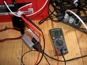
I've done some current measurements on our inverter while using different items to map how much power each thing uses. I attached the multimeter before the inverter so that the power the inverter consumes is also included in the results. Here's a table of the items measured.
| Item | Current | Power |
|---|---|---|
| Nothing | 160mA | 1.92W |
| LED Light | 380mA | 4.56W |
| Net (Hub & 3G router) | 700mA | 8.4W |
| Dell adapter | 310mA | 3.72W |
| Dell (on, not charging) | 1.45A | 17.4W |
| Dell (on, charging) | 2.45A | 29.4W |
| Dell (off, charging) | 1.13A | 13.56W |
| Lenovo adapter | 210mA | 2.52W |
| Lenovo (on, not charging) | 1.13A | 13.56W |
| Lenovo (on, charging) | 2.82A | 33.84W |
| Lenovo (off, charging) | 2.92A | 35.04W |
A couple of interesting things show up here, firstly, the inverter actually uses about 2W of power when nothing is being used, so it would be best to include a switch for that in a handy location so that we can turn it off throughout the night to save around 20 Watt-hours. It wastes less power when it's being used as can be seen by the fact that our 4.2W light shows 4.56W being used which means the inverter is then only using 0.36W.
The next surprising thing is that the computer power adapters also use a lot of power when not in use and so should not be plugged in if the computer batteries don't need to be charged. My adapter consumes over 3.7W and Beth's over 2.5W when not powering anything.
The charging of the computer batteries consumes a lot of power, but does so for less time than what it took the computer to use that power from its battery - how efficient this is we don't know yet, but in general it's best to avoid wasting the computer battery.
The power consumed by the computer in normal operation is actually quite a bit less than I was expecting, I thought it would be around 30-40W but is actually only 17.4W. The net hub and router are about what I was expecting at 8.4W, I estimated it should be under 10W.
On a typical day at the land we'd have the computer and net running for about six hours and the light running for around four hours, plus a few extra items such as charging and inverter power brings us to about 200 watt-hours per day for our current consumption. On overcast days we're only bringing in about 40W of power from the panels, but for around eight hours of reasonable light that gives us over 300 watt-hours, so we should be in credit with our consumption habits I think :-)
Petrol generator
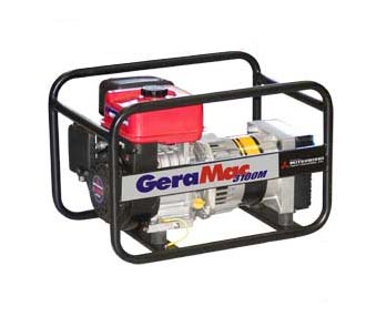
Petrol's not exactly a sustainable independent solution! but having a few kilowatts available in a portable format can sometimes be invaluable especially in the early stages when other more independent solutions are not yet ready. Also a high power inverter is very expensive and we're unlikely to be purchasing one for quite some time, if at all. So for when we need to use power tools, we use our GeraMac 3100M 3KW petrol generator which has a Mitsubishi engine made in Japan and cost about R$1000. It's been really reliable and starts easily every time, even in very cold weather. It has output connections for 115vac, 230vac and 12vdc.
Solar panels
If we consider a worst-case of about four hours of sun per day (which is about right for winter in Rio Grande do Sul) and we want at least 600W hours of power per day then we need at least 150W of panels initially. I'd like to double this reasonably soon and eventually have 1KW of panels so that we can afford to be less frugal with our power, for example by beaing able to keep the computers running when we're not using them so that we can receive incoming calls etc.
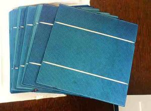
We're going to start with a basic 152W kit like this (I also found this one which is a bit cheaper). Building our own panels from the a kit of individual cells gets the price down to around R$2.40 per Watt which is about half of the best prices available in Brazil for ready-made solar panels.
Having our panel mounted on or near the house isn't really very practical in our situation because we're in a bit of a valley and also have many tall trees near by on all sides. Since we have installed a long power cable up to the top of a near by hill for our rural net connection it seems a practical choice to also use that location for our solar panel.
The only problem with this is that we don't want the net hub and router to be constantly on, we want to be able to turn it on and off from the house, but if the panel, battery, charge-controller and inverter are all situated at the remote end of the power cable we can't simply connect or disconnect the power from the net circuit like we could if it were located at the house end.
A reasonably simple solution could be to put a switch at the house-end of one of the spare pairs in the LAN cable. The switch would be used to control a Solid-state relay in the middle pole that activates the hub, and another at the end that activates the router. Only a very low voltage and current then needs to be running through the LAN pair with the switch on it.
Soldering the cells together
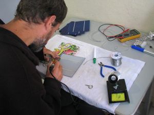
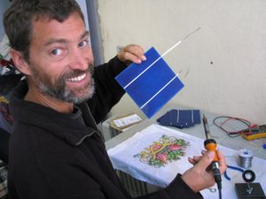
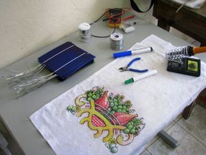
I watched this video to learn how to assemble the cells into a functional panel. The first step is to solder the tabbing wire onto the backs of all the cells; each cell is 0.5 volts with the backs positive and the fronts negative, so the idea is to wire all forty cells in series which makes a panel with a maximum output of 20 volts and a nominal output of around 16 volts. This output is then feed into the charge controller which adjusts it to suit the battery and load state.
|
|
|
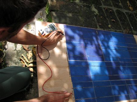
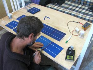
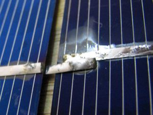
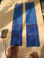
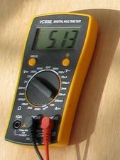
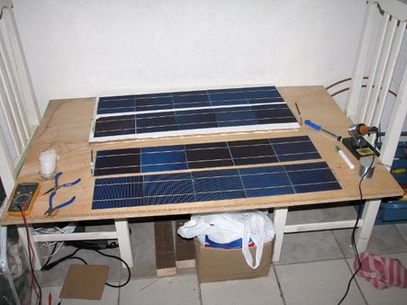
Next I started soldering the cells together into groups of five in series by attaching the tabbing wire that had previously been soldered to the backs to the fronts. One problem that came up with this procedure was that I discovered that I actually have three different types of panels! they're all the same size, but there's two slightly different widths between the connection strips, which meant I had to do some dodgy connecting of some of the cells as shown in the second picture below. The final pictures show a voltage measurement on a series of ten cells which is reading correctly at just over 5 volts.
|
|
|
|
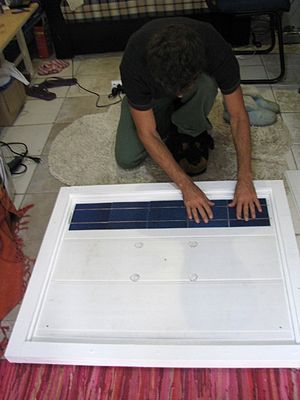
I've now got all four rows of five cells soldered together to make the first panel. I temporarily joined them to test the voltage and it's looking good at 10.59 volts :-) The cells are incredibly fragile and I've broken some small bits of some and have some cracks in others, it's like trying to solder together slim potato chips! Not all cells are quite as fragile as this though, one of the three types I've got feels a lot sturdier, so I hope that
the next set of forty I purchase will all be the same and of the more sturdy type.
Assembling the frames
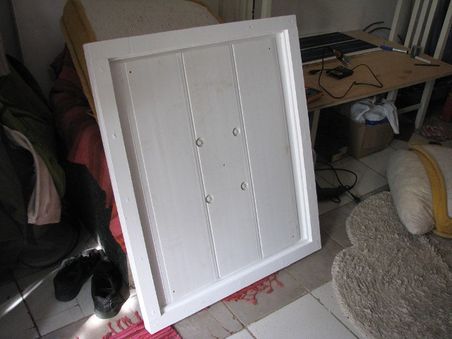
First I got a large sheet of weather-proof ply wood and got it chopped into four equal pieces of 80cm by 120cm which is enough for three panels (I only have enough cells for two panels so far though). Each cell actually only needed to be 80x94 though so these were then cut a bit more.
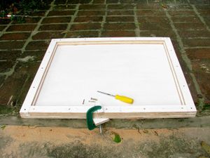
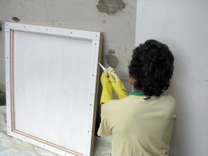
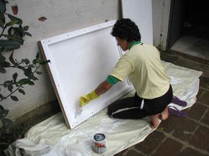
I then cut four long pieces of the ply 6cm wide and another four 5cm wide pieces to form a frame for the glass to sit in. I used a G-clamp to hold the frame pieces in position while drilling the screw holes, and to hold it together tightly while putting each screw in to help ensure that its water-tight, and then Beth put silicone sealant into the remaining cracks before painting it.
|
|
|
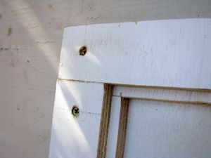
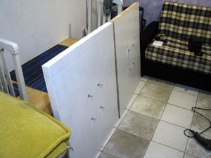
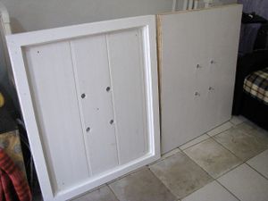
Now that the first frame is painted and dried, we can put some bolts in for mounting the panel securely, put some plastic on to hold the panels away from the bolts and from the wood which can expand and contract a bit with changes in the temperature, and put the power cable through in a secure and water-tight way. I decided to do the first panel completely before doing anything more on the second panel in case I come across problems or find better ways of doing it along the way. For example, I've discovered that sealing the cracks with putty would be better than silicone because the silicone won't allow the paint to stick to it. Also, on the next one I would make the counter-sink holes slightly deeper so that I could putty over all the screws to make them more water-tight and invisible too.
|
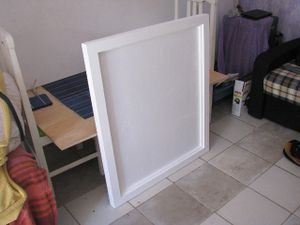
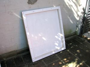
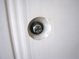
The second frame is now ready for putty and paint. You can see here that I've made the counter-sinking a bit deeper. I then drilled four holes into each panel and put sturdy bolts through the so we have a good strong means of mounting them later.
|
|
|
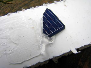
The first panel being all painted and dried was then ready to have some cells put into it :-) First I screwed a plastic base onto the frame with holes drilled into it to make way for the bolts. The plastic is to avoid the cells being directly on the wood which may get moisture on it and can bend or expand and contract in differing weather conditions. The plastic was also useful for raising the surface so the cells aren't in contact with the bolts. Before actually bonding the cells to the plastic, I thought it would be best to test that the silicone we're using would bind well to them both, so I took a small piece of cell that had broken off one of the corners when I was soldering them together and did a test which showed that the silicone is indeed a good choice :-)
|
|
|
Installing and wiring the cells
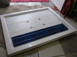
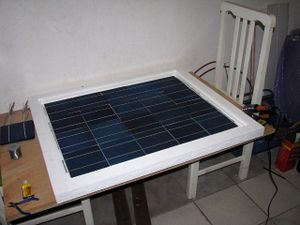
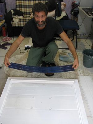
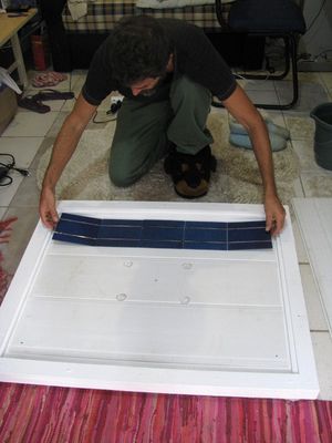
And finally, the process of actually getting the cells into the frame. I first marked with pencil on the plastic a grid so I could position each row of cells accurately, and then put a couple of lines of silicone on the plastic for each of the five cells in a row. I then picked up a row of five that had been soldered together a few weeks ago and carefully placed it in position and slowly moved it in a small circular motion pressing very gently on each cell to get the silicone bonding nicely with both the plastic surface and the cells.
|
|
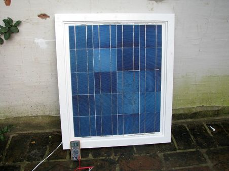
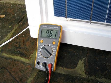
Here's the first panel all wired up and the voltage tested and showing at a little under 10 volts - which is right for a fairly overcast grey day :-)
|
|
And now the same process for the second panel...
|
|
|
|
|
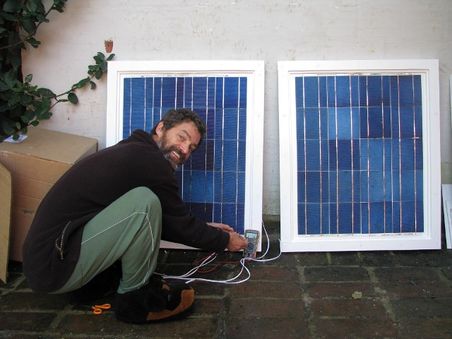
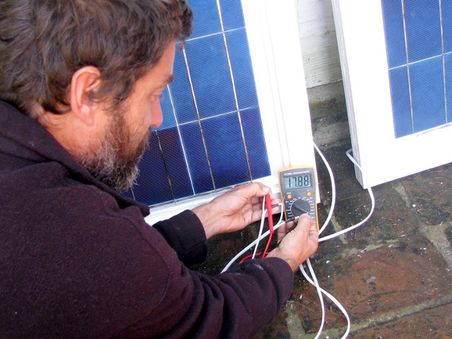
And then we do some final tests to ensure they're both working correctly before calling the glass guy :-) here's both panels wired together in series with the voltage showing as 17.88 which is very good since they're in the shade with no direct sun light on them anywhere.
|
|
Installing the glass
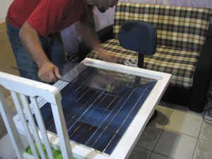
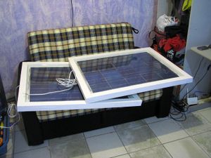
And finally putting the glass in! it only cost an extra R$5 for the glass guys to come over and measure everything and then bring the glass here to us, and then they install it for free so we decided we may as well let them do it :-)
|
|
Solar panels 2.0
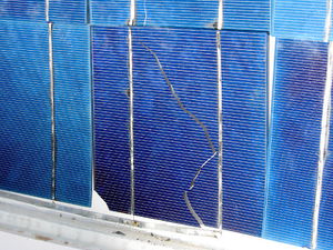
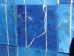
The first panel design has some problems which allowed moisture to accumulate on the inside and also has allowed the cells to bend and crack. They seem to have settled to a final position where no more damage is occurring, but some of them have cracked all the way across, other have just small bits broken off.
|
| | | 
|
I'm ording another forty or maybe eighty cells from this place which is doing packs of forty for R$289. This time I'm going to do the design slightly differently whereby the cells will be placed face down onto the glass and then glued in place with silicon on the backs and edges of the cells. Then the plywood backing and the glass will be held only slightly separated by some spacing material around the edges and bolted together. The spacing will be inset slightly from the edges to allow for silicon to be put all around the edge to keep it water-tight. A silicon moisture absorber will be placed inside the panel as well to ensure no moisture can accumulate on the glass or cells. A soft matt material will be placed behind the cells to keep them from direct contact with the ply and also to held them firmly in position so there's no way for them to bend.
Charge controller
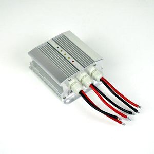
The sources of power such as the solar panels don't connect straight to the battery because this can damage the battery if it's already fully charged, or if the voltage coming from the panels is too high or too low. So instead the power sources must first connect to a charge controller which assesses both the source power and the battery state and conditions the power to the battery's requirements. Charge controllers have two terminals to connect to the power source, two for the battery and most have another two for the load (i.e. the equipment you want to run). The reason for the separate load connections is so that the charge controller can completely disconnect the battery from the circuit if it's fully charged, but still supply a high current to the load.
Our charge controller is the SML-60 from MovTec here in Curitiba (Rua Carmem Maito Stinglin, 80, ph. 30145114). We decided on the SML-60 because we'll be running a 12V system which means that the SML-25 would only be able to handle 300W which is less than another one of our current 152W sets of cells. The SML-60 can handle 720W which means four of or 152W modules will be no problem at all for the unit to handle.
I think that sometime in the near future it would be worth investing in the more expensive MPPT type of charge controller because then we can efficiently utilise power from any source regardless of the voltage (as well as getting the most out of our solar cell's output as well). Not only does an MPPT charge controller ensure that no portion of the input power is wasted, it also dynamically tests the characteristics of the panel which changes as the light conditions change to ensure that the current and voltage being drawn from the panel are at the most optimal efficiency - i.e. the Maximum Power Point.
Our charge controller is giving incorrect results for the battery state, it seems to be showing the input state instead and is also affected by the amount of output being drawn. The manual is not very helpful and seems to have a section missing which is supposed to describe how to configure it by setting the jumpers inside. I found this manual which has a similar circuit board with the same jumpers, so I'll try basing the configuration on that one - if it's correct then it shows that two of our jumpers need to be changed, the first was set to gel battery type instead of fluid, and the second to voltage-controlled disconnect instead of state-of-charge controlled.
I've decided I'm going to build my own MPPT charge controller using a Raspberry Pi based on this DIY Arduino-based MPPT charge controller project.
Battery
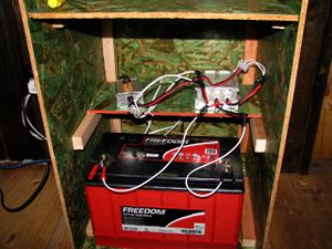
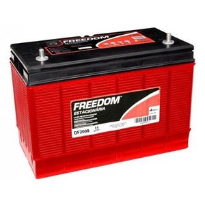
We've been looking for a battery suitable for using with our solar panel and whatever other sources of pwer we end up using and the charge controller, but we've had a lot of trouble finding anything for a practical price. Then when we were going to a cafe to meet one of Beth's friends we saw a small battery shop on the other side of the road, so we decided to pop in and ask if they had anything, or if not, if they knew of anywhere we could go. Well it turned out that the place was actually very large inside and had a huge range of batteries including the exact kind we were looking for at a good price :-) and better still it turns out that the owner travels to Canela each weekend and said he can drop it off at the Pensão for us! This was really good luck because it weights over 27Kg and batteries require a special expensive courier service to transport. We got a 115Ah Freedom DF2000 battery for R$440. The DF2000 is a fluid electrolyte battery which allows for better thermal dissipation and are sensitive to temperature variation than gel (VRLA) batteries.
Power inverter
Since most normal lighting and appliances such as laptops, phone chargers and routers all run off 110 or 220 volts AC, we need an "inverter" to convert to this high AC voltage from the 12 volts DC coming from the battery. There's quite a range of inverters available from very cheap to very expensive. Th most expensive ones are required if you need very high power and/or very perfect "pure sine" wave-form in your output. We don't need either of these things because all our appliances use their own power adapters to provide them with the exact specifications of power they require, and our LED lights aren't fussy either, so for us the very cheap options are available :-)
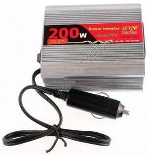
We got a cheap 200W inverter from dx.com for only US$20 and free delivery to Brazil. This will be fine for our requirements, and for the rare times that we need to use power tools, we can use the generator. Most of these cheap ones come with a car cigarette-lighter plug for input because they're designed to be used in the car so you can charge your laptop or phone when you're on the road. We have a cigarette-lighter socket which we'll attach to our battery so that we can easily unplug the inverter and take it with us in the car if we ever need to.
Wind & Water
We'll eventually get a small wind turbine and water wheel set up, but we'll start with the solar and work on these later. The common factor in both of these is the generator. I want to get in to building my own after I downloaded Energy Creator's DVD and found that building really efficient generators of a few hundred watts of power is totally doable and quite cheap.
Tesla coils
After reading some of the 2600 page Practical Guide to Free-Energy Devices eBook, I really want to try some of the simpler designs out for myself.
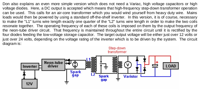
The first being one of Don Smith's designs on page 236:
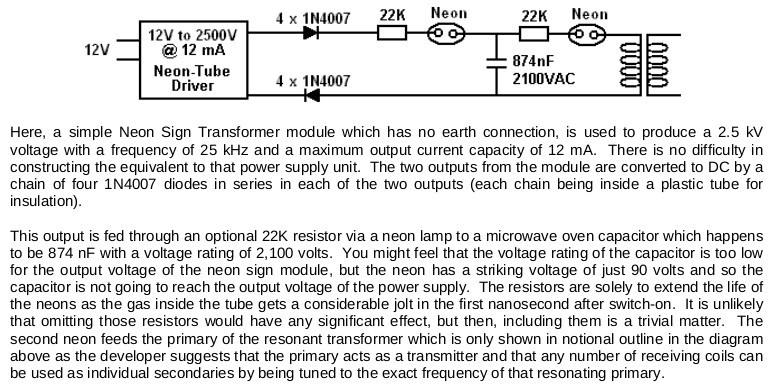
The second is another of Don Smith's designs on page 248:
Tesla aerials
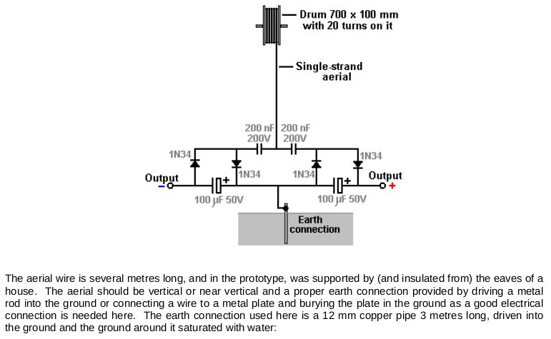
And I've always found the Tesla Aerials pretty interesting which are discussed starting on page 586.
|
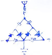 Whiteboard notes from 2011 |
See also
- Moving on to our land
- Our rural net connection
- Energy
- Gravity light - cool crowd-sourcing project for creating lighting from a lifted weight
- LED over 100% efficient
